


Wiring assistance.
Started by
xlambx
, Jan 31 2007 05:51 PM
#1

 Posted 31 January 2007 - 05:51 PM
xlambx
-
- Member
-

- 62 posts
Member

#2
Posted 31 January 2007 - 08:12 PM
Jack123
-
- Retired Staff
-

- 944 posts
Trusted Tech
01- Lambert Nguyen[Wiring Problem]-Jan 31st 2007
This is the System Panel Connector which connects your Motherboard to all of your Front Panel Indicators Switches & other Goodies Usually it would be a 20 Pin Connector
Looks like your new Motherboard is for a Server Work Station Does your Case have the 2 Ethernet LEDs - ?? That is what the extra 4 pins control
Your Manual should describe requirements & support information Also you should visit the Motherboard website look for Accessories Page Requirement Page Support Page
I would need to have more Info on your Update System -
(1) Manufacturer & Model Number of Motherboard
(2) Manufacturer & Model Number Case
(3) Probably would be helpful to know info on Old Equipment that is being updated
Maybe browse thru the System Building & Upgrading Forum Just south of Hardware
on Geeks 2 Go - You may see similar issues
It just appears that your case lacks support for this Motherboard/Main Board We just need to identify where problem is Post back the requested info & I can give you more details -
Jack123
Edited by Jack123, 31 January 2007 - 08:14 PM.
#3
Posted 31 January 2007 - 08:32 PM
xlambx
- Topic Starter
-
- Member
-
- 62 posts
Member
Actually the picture that I found was not an "exact" image of what mine looks like. Mine only has 20 pin holes, 10 on top of each other. My old motherboard came from the old Dell Dimension 2350, but the new one is a MSI MB K8TNEO-V. My processor is upgraded from a INTEL P4 to a AMD Athlon 64 3000+ Socket 754. Do you know where I can go and purchase a System Panel Connector?
MSI MB K8TNEO-V
Part# BL3000K8TNV
SKU# 337506
Mft Part Number: 7032-020 K8T NEO-V
MSI MB K8TNEO-V
Part# BL3000K8TNV
SKU# 337506
Mft Part Number: 7032-020 K8T NEO-V
Edited by Lambert Nguyen, 31 January 2007 - 08:35 PM.
#4
Posted 31 January 2007 - 11:33 PM
Jack123
-
- Retired Staff
-
- 944 posts
Trusted Tech
02- Lambert Nguyen[Wiring Problem]-Jan 31st 2007
Dell is a Proprietary Manufacturer which means that they have their own Standards
I would be Concerned about the Power Connector Dell has changed the Pin Configuration I do not know if MSI manufacturers Dell Replacement Boards with Dells Layout & specification
Are you using a Dell Case ?? and Original Dell provided Power Supply?? If you are BEWARE -
What is different about this System Connector? This may be an Omen I hate to have you burn out your new Motherboard Give me more details on exactly your replacement process And what about the Power Supply Is it adequate & is it a Dell Specified Wiring ? Also you may need more cooling when you do significant changes
You may be OK but when things look different they may be wired different Dell is just another 4 Letter Word to me
Give me a complete list of your changes I will research the specifications for compatibility Give me more details on the PC Case/s PC Power Supply/ies
It will take me a day or two after I have the info I know you are anxious to complete the upgrade but I think you need to consider the error possibility here
Jack123
My old motherboard came from the old Dell Dimension 2350
Dell is a Proprietary Manufacturer which means that they have their own Standards
I would be Concerned about the Power Connector Dell has changed the Pin Configuration I do not know if MSI manufacturers Dell Replacement Boards with Dells Layout & specification
Are you using a Dell Case ?? and Original Dell provided Power Supply?? If you are BEWARE -
What is different about this System Connector? This may be an Omen I hate to have you burn out your new Motherboard Give me more details on exactly your replacement process And what about the Power Supply Is it adequate & is it a Dell Specified Wiring ? Also you may need more cooling when you do significant changes
You may be OK but when things look different they may be wired different Dell is just another 4 Letter Word to me
Give me a complete list of your changes I will research the specifications for compatibility Give me more details on the PC Case/s PC Power Supply/ies
It will take me a day or two after I have the info I know you are anxious to complete the upgrade but I think you need to consider the error possibility here
Jack123
#5
Posted 01 February 2007 - 10:06 AM
xlambx
- Topic Starter
-
- Member
-
- 62 posts
Member
I am not using an original Dell case or Power Supply. About half a year ago or something, I got a new case as a present. So I switched everything from the Dell case, over into the new case. And it also came with a new power supply as well, 450 Watts. When I got my new case, I just plugged the power supply into my motherboard and it was fine. So I think the power supply is good I hope? Here's the link to my case.
http://www.microcent...oduct_id=232152
The difference between the connectors, is that for my old motherboard, it use to be like a solid 2 lines each with 10 pin slots, like the picture from my first post. But the new motherboard has it so it's not in a straight line, About two rows 4 pins in a group, then the other half is adjacent to it with 2 rows of 5 pins. The one going down is labeled JFP1, and the one going across is JFP2.
oo
oo
oo
oo
oo
oooo
oooo
Here was my way of trying to draw it out >.<. But i found a download of the manual online.
http://us1.msi.com.t...u/M7032v1.1.zip
I don't know if you're going to download it, but if you do, on page 5 is a layout of my motherboard. On the bottom right corner, I don't know if you can see it, but there are two slots and that's where the frontpanel connectors are supposed to go.
***
I just actually copied and pasted the connector section from the .pdf right after posting. So this part is an edit. Here is my new motherboards layout of the frontpanel connectors.

And my old Dell one just went in a row like this:
oooooooooo
oooooooooo
http://www.microcent...oduct_id=232152
The difference between the connectors, is that for my old motherboard, it use to be like a solid 2 lines each with 10 pin slots, like the picture from my first post. But the new motherboard has it so it's not in a straight line, About two rows 4 pins in a group, then the other half is adjacent to it with 2 rows of 5 pins. The one going down is labeled JFP1, and the one going across is JFP2.
oo
oo
oo
oo
oo
oooo
oooo
Here was my way of trying to draw it out >.<. But i found a download of the manual online.
http://us1.msi.com.t...u/M7032v1.1.zip
I don't know if you're going to download it, but if you do, on page 5 is a layout of my motherboard. On the bottom right corner, I don't know if you can see it, but there are two slots and that's where the frontpanel connectors are supposed to go.
***
I just actually copied and pasted the connector section from the .pdf right after posting. So this part is an edit. Here is my new motherboards layout of the frontpanel connectors.
And my old Dell one just went in a row like this:
oooooooooo
oooooooooo
Edited by Lambert Nguyen, 01 February 2007 - 10:15 AM.
#6
Posted 01 February 2007 - 03:43 PM
Jack123
-
- Retired Staff
-
- 944 posts
Trusted Tech
03- Lambert Nguyen[Wiring Problem]-Feb 1st-2007
Ok describe what the Case Mating Connectors from Front Panel look like - Usually they are single connectors How many do you have
Jack123
Ok describe what the Case Mating Connectors from Front Panel look like - Usually they are single connectors How many do you have
Jack123
Edited by Jack123, 01 February 2007 - 03:43 PM.
#7
Posted 01 February 2007 - 05:22 PM
xlambx
- Topic Starter
-
- Member
-
- 62 posts
Member
What do you mean Case Mating Connectors?
#8
Posted 02 February 2007 - 04:27 PM
Jack123
-
- Retired Staff
-
- 944 posts
Trusted Tech
04- Lambert Nguyen[Wiring Problem]-Ground Hog Day-2007
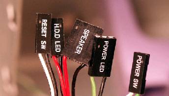
I mean the Harness [Bundle of Wires] That are attached to your Front Panel Components that Connect to the to JFP-1 & JFP2 Connectors on the Motherboard You showed photo/sketch of the Motherboard Connectors I want to see what connector/s you are trying to connect them with
The Link to your Tower I could not see that harness too well But it looked like there were several individual connectors Usually the 2 LEDs Power Switch Reset Switch are separate wiring The USB Audio LAN Firewire Connectors plug into their own Header Assembly -
It looks as if your new Motherboard supports more Front Panel Components than the your old board See the way it goes The Case Manufacturer is responsible for the Wire Harness & Connectivity for Front Panel Power Supply Wiring Fan Wiring Drive Wiring Peripheral wiring to the Motherboard The Motherboard provides the Peripheral Support and provides a Motherboard Connection
You probably have some additional Front Panel connectors that were included in the Box that your Case came in
_______________________________________________________________________
Apparently your Case & Old Motherboard were Compatible And this is my concern about the Dell Being that the Power Supply was supplied with the Case it was also compatible with the Dell No Problem
However The Case & Power Supply may not be compatible with New Motherboard This gets us back to my issues noted in my 2nd post I know that the Case & PS stated ATX Compatible but Dell has had different ATX Standards in the past -
It looks as if your Power Supply Connector is a 20 Pin connector - ?? Is there a second Power Connector also??
If so how many pins -
I would like to settle this compatibility Issue before making adapter connectors There is a reason for the connection issue
Post back answers to Power Supply Connectors
Jack123
What do you mean Case Mating Connectors?
I mean the Harness [Bundle of Wires] That are attached to your Front Panel Components that Connect to the to JFP-1 & JFP2 Connectors on the Motherboard You showed photo/sketch of the Motherboard Connectors I want to see what connector/s you are trying to connect them with
The Link to your Tower I could not see that harness too well But it looked like there were several individual connectors Usually the 2 LEDs Power Switch Reset Switch are separate wiring The USB Audio LAN Firewire Connectors plug into their own Header Assembly -
It looks as if your new Motherboard supports more Front Panel Components than the your old board See the way it goes The Case Manufacturer is responsible for the Wire Harness & Connectivity for Front Panel Power Supply Wiring Fan Wiring Drive Wiring Peripheral wiring to the Motherboard The Motherboard provides the Peripheral Support and provides a Motherboard Connection
You probably have some additional Front Panel connectors that were included in the Box that your Case came in
_______________________________________________________________________
Apparently your Case & Old Motherboard were Compatible And this is my concern about the Dell Being that the Power Supply was supplied with the Case it was also compatible with the Dell No Problem
However The Case & Power Supply may not be compatible with New Motherboard This gets us back to my issues noted in my 2nd post I know that the Case & PS stated ATX Compatible but Dell has had different ATX Standards in the past -
Dell is a Proprietary Manufacturer which means that they have their own Standards
It looks as if your Power Supply Connector is a 20 Pin connector - ?? Is there a second Power Connector also??
If so how many pins -
I would like to settle this compatibility Issue before making adapter connectors There is a reason for the connection issue
Post back answers to Power Supply Connectors
Jack123
Edited by Jack123, 03 February 2007 - 09:13 AM.
#9
Posted 02 February 2007 - 04:37 PM
xlambx
- Topic Starter
-
- Member
-
- 62 posts
Member
THe wires coming out of the power supply only has a 20-pin connector, and on the motherboard, there is only a connecting head for a 20-pin connector.
And for the frontpanel question you asked me, There are 6 wires that need to be connected. each with a positive and negative, so 3 groups of wires with 2 in each, the LED power light, the power switch, and reset switch.
And for the frontpanel question you asked me, There are 6 wires that need to be connected. each with a positive and negative, so 3 groups of wires with 2 in each, the LED power light, the power switch, and reset switch.
#10
Posted 02 February 2007 - 04:57 PM
Jack123
-
- Retired Staff
-
- 944 posts
Trusted Tech
05- Lambert Nguyen[Wiring Problem]-Ground Hog Day-2007
OK
3 groups of wires with 2 wires per group for a total of 6 wires
Do all 6 wires terminate into just 1 connector or does each group terminate into 2 pin connectors -
Jack123
And for the frontpanel question you asked me, There are 6 wires that need to be connected. each with a positive and negative, so 3 groups of wires with 2 in each, the LED power light, the power switch, and reset switch.
OK
3 groups of wires with 2 wires per group for a total of 6 wires
Do all 6 wires terminate into just 1 connector or does each group terminate into 2 pin connectors -
Jack123
Edited by Jack123, 03 February 2007 - 01:12 PM.
#11
Posted 02 February 2007 - 05:04 PM
xlambx
- Topic Starter
-
- Member
-
- 62 posts
Member
All 6 of the wires go into 1 20-pin connector.
#12
Posted 03 February 2007 - 02:28 PM
Jack123
-
- Retired Staff
-
- 944 posts
Trusted Tech
06- Lambert Nguyen[Wiring Problem]-3rd Feb-2007
Front Panel Connection Terminology
Motherboard Connection are rows of Male pins soldered on Motherboards that come in Single or Dual Rows The spacing may be 0.1-Inch or 0.2-Inch spacing These are known as Pin Header Assembly
Harness Connections - These are the Plug Type Connectors with wires attached They are called
Terminal Housing They come in Single or Dual and also have 0.1-Inch or
0.2-Inch Spacing -
__________________________________________________________________________________
To modify the existing 20 Pin Connector You need to obtain
(1) - 10 Pin [Terminal Housing] that matches JFP1 Pin Header Assembly
(2) 8 Pin [Terminal Housing] that matches JFP2 Pin Header Assembly
(3) Pin Extractor for removing 6 wires of the existing 20 Pin Terminal Housing
Then it is just a matter of extracting the wires from the existing 20 pin connector & inserting them in the proper 10 pin & 8 pin Terminal Housing
Seems to me That you should have 8 wires ???
See Attached Thumbnail wiring sketch 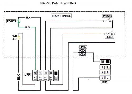
I think there are single Terminal Housing connectors terminated with a 8-Inch wire with pin that will mate with the 20 Pin Connector (You would need 6 of these) to make an adapter cable
See thumbnail -
If you work in company that has Office Computers Maybe you can check with one of the Network Techs
or stop in & chat with a Computer Repair Shop Or if you have a Hobby Electronics Store in your Area-
Jack123
http://www.jammaboar...tors/cat_4.html
http://www.jameco.co...e...1&langId=-1
Front Panel Connection Terminology
Motherboard Connection are rows of Male pins soldered on Motherboards that come in Single or Dual Rows The spacing may be 0.1-Inch or 0.2-Inch spacing These are known as Pin Header Assembly
Harness Connections - These are the Plug Type Connectors with wires attached They are called
Terminal Housing They come in Single or Dual and also have 0.1-Inch or
0.2-Inch Spacing -
__________________________________________________________________________________
To modify the existing 20 Pin Connector You need to obtain
(1) - 10 Pin [Terminal Housing] that matches JFP1 Pin Header Assembly
(2) 8 Pin [Terminal Housing] that matches JFP2 Pin Header Assembly
(3) Pin Extractor for removing 6 wires of the existing 20 Pin Terminal Housing
Then it is just a matter of extracting the wires from the existing 20 pin connector & inserting them in the proper 10 pin & 8 pin Terminal Housing
Seems to me That you should have 8 wires ???
See Attached Thumbnail wiring sketch

I think there are single Terminal Housing connectors terminated with a 8-Inch wire with pin that will mate with the 20 Pin Connector (You would need 6 of these) to make an adapter cable
See thumbnail -
If you work in company that has Office Computers Maybe you can check with one of the Network Techs
or stop in & chat with a Computer Repair Shop Or if you have a Hobby Electronics Store in your Area-
Jack123
http://www.jammaboar...tors/cat_4.html
http://www.jameco.co...e...1&langId=-1
Edited by Jack123, 03 February 2007 - 02:33 PM.
#13
Posted 03 February 2007 - 02:38 PM
Jack123
-
- Retired Staff
-
- 944 posts
Trusted Tech
07- Lambert Nguyen[Wiring Problem]-3rd Feb-2007
Check the color coding of your 20 Pin Power Supply Connector with this sketch
Jack123
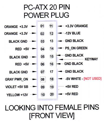
Check the color coding of your 20 Pin Power Supply Connector with this sketch
Jack123

Edited by Jack123, 13 February 2007 - 12:17 PM.
#14
Posted 03 February 2007 - 08:29 PM
xlambx
- Topic Starter
-
- Member
-
- 62 posts
Member
Check the color coding of your 20 Pin Power Supply Connector with this sketch –
My colors are exactly like that, except where you put it says "white", there is not a wire for me where it says "white".
Edited by Lambert Nguyen, 03 February 2007 - 08:41 PM.
#15
Posted 04 February 2007 - 08:26 AM
Jack123
-
- Retired Staff
-
- 944 posts
Trusted Tech
08- Lambert Nguyen[Wiring Problem]-4th Feb-2007
That is fine
It is an older Voltage, that is not necessary today The smaller Form Factor Supplies SFX do not
include the [5 Volts] It was shown for Backward Capability
If your Power Wiring Matched everywhere else Then you are OK Sorry for dragging that issue into your Post but I am an Old Coal Miner That was taught to Tread Softly &
Watch the Canary Warnings
Jack123
My colors are exactly like that, except where you put it says "white", there is not a wire for me where it
says "white".
That is fine
It is an older Voltage, that is not necessary today The smaller Form Factor Supplies SFX do not
include the [5 Volts] It was shown for Backward Capability
If your Power Wiring Matched everywhere else Then you are OK Sorry for dragging that issue into your Post but I am an Old Coal Miner That was taught to Tread Softly &
Watch the Canary Warnings
Jack123


Similar Topics
0 user(s) are reading this topic
0 members, 0 guests, 0 anonymous users
As Featured On:


 Sign In
 Create Account
