Jump to content

Welcome to Geeks to Go - Register now for FREE

Need help with your computer or device? Want to learn new tech skills? You're in the right place!
Geeks to Go is a friendly community of tech experts who can solve any problem you have. Just create a free account and post your question. Our volunteers will reply quickly and guide you through the steps. Don't let tech troubles stop you. Join Geeks to Go now and get the support you need!

How it Works Create Account
Photo

Newly Assembled Desktop Won't Power On?


  • Please log in to reply

#1
howtheflip

howtheflip

    Member

  • Member
  • PipPip
  • 85 posts
Hello all. I recently ordered parts to build my first computer on Cyber Monday, and all parts (except the CPU) have arrived. I figured I could still assemble everything else without the CPU just so that when it comes I can drop it in and start right into it. So today I assembled everything and after a while of cable management and plugging everything in I thought I as done. So, in order to test to see if everything was plugged in, I figured I'd just power it on, because it should boot even without the CPU. So I closed the case up and plugged the power in and nothing happened. I relooked over the wires to see if I missed anything, but it's not standing out to me.

I attached 7 images to this to show you what I mean when I describe everything I checked, so you could take a look to see that it's right/wrong and let me know if I missed anything.

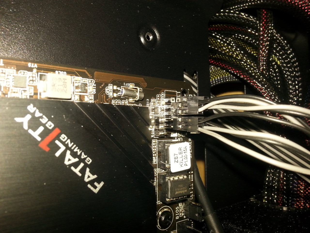
I started with the LED/Power Switch/Reset Button wires. My motherboard manual shows that grey wires are positive, and like much motherboards, that meant that the writing on the wires was pointing down. I had LED + and then - on top, followed by the Power Button +/- next to it. It only had 4 prongs on top so all of them were taken.
Below, it Went HDD +/-, an open spot (marked as ground in my manual, and then the Power Reset +/-.
The only thing I noticed that was odd is that my manual shows LED +,-, Power, ground as the four top prongs, but my Power is 2 prongs long, so the negative end is plugged into the ground? That is the same with the bottom, with it going HDD LED +,-, Ground, Power Reset, Ground, with my power reset being two prongs so the - lead is in the ground.

The only other thing I could think: The 24 pin power supply is plugged in, with the 4 pin one right next to it. That looks right to me, but maybe it is loose or something?


The 2 4pin CPU wires have been plugged in firmly, even without the CPU so I don't think this is the issue either way.
The SATA cables have been plugged in on both ends, but once again wouldn't be the issue.
The USB 3.0 cable is plugged in, which shouldn't be the issue.
All 3 Fans are plugged into the fan controller, and then the fan controller is plugged into the molex power supply. Which shouldn't be the issue.
The HD audio is plugged in.
The USB 2.0 is plugged in.
I have plugged the Power to each hard drive as well.
The PCI-e wire is sitting to be plugged in when my GPU arrives.

That is all I have for information, I will continue to look at it for a bit and any advice would be greatly appreciated. Thanks

Attached Thumbnails

  • IMG_20131211_145300.jpg
  • IMG_20131211_145306.jpg
  • IMG_20131211_145311.jpg
  • IMG_20131211_145316.jpg
  • IMG_20131211_145320.jpg
  • IMG_20131211_145335.jpg
  • IMG_20131211_145342.jpg

  • 0

Advertisements


#2
phillpower2

phillpower2

    Mechanised Mod

  • Global Moderator
  • 24,749 posts
Hello howtheflip

A computer cannot/will not boot without a suitable CPU present and the same if no Ram or graphics solution was detected, the computer will simply fail the POST (power on self test) please see information below;

What happens between the time that you power up the computer and when the icons appear on the desktop;

In order for a computer to successfully boot, the BIOS, operating system and hardware components must all be working properly; failure of any one of these three elements will likely result in a failed boot sequence.

When the computer's power is first turned on, the CPU initializes itself, which is triggered by a series of clock ticks generated by the system clock. Part of the CPU's initialization is to look to the system's ROM BIOS for its first instruction in the startup program. The ROM BIOS stores the first instruction, which is the instruction to run the power-on self test (POST), in a predetermined memory address. POST begins by checking the BIOS chip and then tests CMOS RAM. If the POST does not detect a battery failure, it then continues to initialize the CPU, checking the inventoried hardware devices (such as the video card), secondary storage devices, such as hard drives and floppy drives, ports and other hardware devices, such as the keyboard and mouse, to ensure they are functioning properly.

Once the POST has determined that all components are functioning properly and the CPU has successfully initialized, the BIOS looks for an OS to load.

The BIOS typically looks to the CMOS chip to tell it where to find the OS, and in most PCs, the OS loads from the C drive on the hard drive even though the BIOS has the capability to load the OS from a floppy disk, CD or ZIP drive. The order of drives that the CMOS looks to in order to locate the OS is called the boot sequence, which can be changed by altering the CMOS setup. Looking to the appropriate boot drive, the BIOS will first encounter the boot record, which tells it where to find the beginning of the OS and the subsequent program file that will initialize the OS.

Once the OS initializes, the BIOS copies its files into memory and the OS basically takes over control of the boot process. Now in control, the OS performs another inventory of the system's memory and memory availability (which the BIOS already checked) and loads the device drivers that it needs to control the peripheral devices, such as a printer, scanner, optical drive, mouse and keyboard. This is the final stage in the boot process, after which the user can access the system’s applications to perform tasks.
  • 0

#3
howtheflip

howtheflip

    Member

  • Topic Starter
  • Member
  • PipPip
  • 85 posts
On further experimenting, I decided to see if just the 20pin connector would work on unplugged the 4pin. I plugged the PSU back in, and I don't know if i'm just seeing things, but I swear the ethernet green light lit up for a second twice? Even without unplugging and plugging it back in, the the light won't come back on again, and the machine still fails to power up.
  • 0

#4
howtheflip

howtheflip

    Member

  • Topic Starter
  • Member
  • PipPip
  • 85 posts
Ah, that is definitely relieving then. So no matter what I do, the computer will not even have running fans or anything of that nature without a CPU installed?

So while I'm at it, I might as well ask: My 20pin cable snaps right in and I can hear it. It does not move when I pull on it at all and takes some force to get out. The 4 pin however, doesn't even seem to fully go in, I do not hear a click, and just a little big of wiggling knocks it out. Is this one supposed to snap in as well? Can I just use the 20pin in leave the 4 pins out, even though my motherboard shows 24 pins? It's a 750w 80+ gold PSU. I just don't know if leaving that out affects the available watts or voltage or anything? All the reading I've done says that those extra 4 pins are to supply reliable voltage to the Graphics card, but if I have a direct connection of power to the graphics card, is that pin actually necessary?

Edited by howtheflip, 11 December 2013 - 02:47 PM.

  • 0

#5
phillpower2

phillpower2

    Mechanised Mod

  • Global Moderator
  • 24,749 posts
Please go back - read thoroughly and make certain that you understand the installation instructions for all of your hardware before you end up with a rather expensive doorstop, anything that you are not sure of please ask and do not be tempted to turn on the power until you are 100% certain things are connected correctly, read the build tutorial provided courtesy of Troy and Artellos respectively, see here

The connections should have a plastic tab that locks the plugs firmly into place.

Both 20/24 and 4/8 pin connections must be plugged in for the system to work, the 20/24 pin provides the main power to the MB and hardware such as the HDDs and video card etc and the 4/8 pin connection provides the +12V power for the CPU.

Tip

If you have something to add while waiting for a reply use the edit tab – bottom right of the dialogue input box and this will ensure that no information that you provide is overlooked (this can happen if your topic has more than one page) thank you for understanding.


  • 0

#6
howtheflip

howtheflip

    Member

  • Topic Starter
  • Member
  • PipPip
  • 85 posts
I am done messing with it for now, from what I can see based on the ethernet light that went on, power is going to the motherboard. And the only reason I asked about the 20+4 pin is because the 4pin doesn't have a clip to snap it into place... but I think I got it in solid now as it is smooth with the other and I will not mess with it. I know for a fact every other pin is in properly, aside from that odd ground situation with the Power button and Power reset button. I have referenced about 3 different guides on how to do it all, as well as my power supply manual and motherboard manual, so I have gotten as much information as possible to make sure it is correct.
  • 0

#7
Brazened

Brazened

    Member

  • Member
  • PipPipPip
  • 184 posts
Are you sure you're using the right 4 pin with the 20 pin? The 4 pin and the 20 pin usually interlock with each other so that they'd go in as one piece.

What is the make and model of the PSU?
  • 0

#8
howtheflip

howtheflip

    Member

  • Topic Starter
  • Member
  • PipPip
  • 85 posts
Rosewill Capstone 750w 80+ gold. And yes, these two wires came tightly taped together with black electrical tape, but they do not snap together either as far as I can tell.
  • 0

#9
Brazened

Brazened

    Member

  • Member
  • PipPipPip
  • 184 posts
Ok, I looked at the pics of the PSU. It showed the 20 pin and the 4 pin in the same harness but no tape. If yours is in the same harness then that would be no problem.
  • 0

#10
iammykyl

iammykyl

    Tech Staff

  • Technician
  • 7,659 posts
Gday.
So we can check the connection from the case switches and LEDs, please give us the Motherboard brand and model, also the case brand and model.
  • 0

Advertisements


#11
howtheflip

howtheflip

    Member

  • Topic Starter
  • Member
  • PipPip
  • 85 posts
Asrock fatal1ty killer z87 1150 and antec gx700 military style case
  • 0

#12
iammykyl

iammykyl

    Tech Staff

  • Technician
  • 7,659 posts
Gday, Thanks for the info.
The wiring in you pictures looks OK, but there was not one for the front header connection for the case switches and LEDs, and from you discretion, not sure you have it correct. Remove the 4 x 2 pin plugs. There should be a small + embossed on the plastic, positive. Below is a pic of the Header and what too plug in. All 4 plugs are connected on this header.
  • 0

#13
iammykyl

iammykyl

    Tech Staff

  • Technician
  • 7,659 posts
Gday.
At the moment you have all the case fans connected to the fan controller. For better cooling control, and safety. I recommend you unplug the cabling to the rear fan. Connect only the little 3 pin plug to cha/fan #1 on the Motherboard. (MB manual Page 10, item #18. It is a 4 pin socket but the 3 pin plug will only go in one way. Having the rear exhaust fan controlled automatically by the MB will ensure that as the temps go up and down, so will the fan speed.

When you install the CPU and cooler, please connect the cooler fan to CPU/fan #1, MB manual page 10, item #3.

Question. When you installed the Motherboard, did you check that there was only a stand off where you put screws in the Motherboard? No extra ones under the board.
  • 0

#14
iammykyl

iammykyl

    Tech Staff

  • Technician
  • 7,659 posts
Gday.
How is the build going? up and running?
  • 0

#15
howtheflip

howtheflip

    Member

  • Topic Starter
  • Member
  • PipPip
  • 85 posts
Good day.

As of right now everything is up and running smoothly.I have all but the rear and side.fan on the switch, but most of the time I leave it all the way up. The power was upside down after looking at it for a while so that was corrected before I ever tried to boot up. The only thing I think might be wrong is that the big red outer button is the reset and the indented black one is reboot. I think I mixed up the wires when plugging them in haha. So when I get around to that I'll switch it. Its not negatively affecting me at the moment though. Thanks for all the help

Edited by howtheflip, 21 December 2013 - 07:40 AM.

  • 0


Similar Topics

0 user(s) are reading this topic

0 members, 0 guests, 0 anonymous users

As Featured On:

Microsoft Yahoo BBC MSN PC Magazine Washington Post HP