Jump to content

Welcome to Geeks to Go - Register now for FREE

Need help with your computer or device? Want to learn new tech skills? You're in the right place!
Geeks to Go is a friendly community of tech experts who can solve any problem you have. Just create a free account and post your question. Our volunteers will reply quickly and guide you through the steps. Don't let tech troubles stop you. Join Geeks to Go now and get the support you need!

How it Works Create Account
Photo

Lenovo Thinkcentre m700 SFF pinout


  • Please log in to reply

#1
dar124

dar124

    Member

  • Member
  • PipPip
  • 87 posts

Hello, I'm looking for some assistance with getting a Lenovo Thinkcentre m700 motherboard wired up in a Cooler Master Centurion 5 case. Hopefully I can get some info as I start this swap!!!

I currently have a HP dc7600 motherboard as my server running WHS 2011 in a generic case. But I want to upgrade before this old hardware starts to fail and give me problems. I have the Lenovo m700 and the Cooler Master case sitting around. So I figured, why not combine them and upgrade!!! The Lenovo board will be newer / better / faster and the Cooler Master case will allow me to fit more HD's inside.

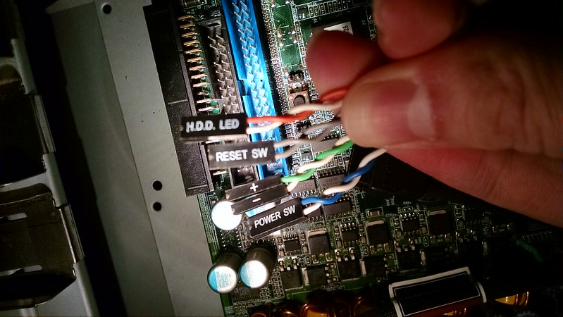
I'm good with the majority of the connections, but I'm not sure which pins to connect the HD activity light, + - led's, power button and reset button wires to?? I previously had a HP xw6200 board in the case and used it as my desktop PC. When the HP board was in the case I had those wires connected to the pins listed below.

hdd led (orange/white) to pins 1 and 3
+ - led's (green/white) to pins 2 and 4
power sw (blue/white) to pins 6 and 8
reset sw (grey wires) to pins 5 and 7


I didn't want to just assume it'd connect to the same pins. Since the info I had was for a HP board and now I'm going to use a Lenovo board. I did google a bit, but didn't have much luck getting any info.  I keep coming up with install manuals or manuals on how to swap out the PSU or CPU. Nothing ever shows the front panel pins. I even searched google images, but I just get stock pics of the motherboard, nothing ever with more detail about the connections.


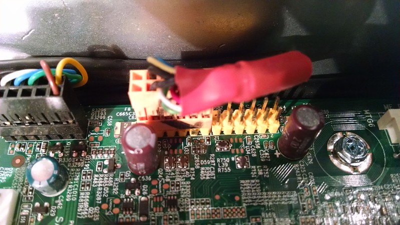
Here's the wires connected to the old HP xw6200 board


30699662850_083327ac96_c.jpg


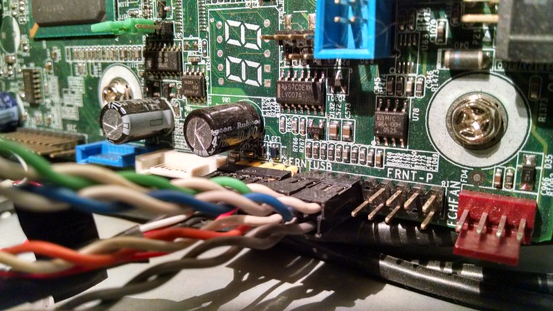
Here's the new pins on the Lenovo board.


30966040456_95ed55755c_c.jpg


And finally the wires that I need to connect.


30699662220_99c274f029_c.jpg


Thanks in advance for any assistance with this!!!


  • 0

Advertisements


#2
zep516

zep516

    Trusted Helper

  • Malware Removal
  • 8,093 posts
1450944298569_zpso3sbrkjr.jpg

I'm not sure if that will help or not
  • 0

#3
dar124

dar124

    Member

  • Topic Starter
  • Member
  • PipPip
  • 87 posts

1450944298569_zpso3sbrkjr.jpg[/url]

I'm not sure if that will help or not


Hey Zep,


Thanks for the response.

I've seen that image before for front panel connections. And I think that is similar to how my old HP xw6200 board was connected in this Cooler Master case.

But I was googling a bit yesterday looking for additional info on this pinout and someone on the Lenovo Forums had a similar question about their Thinkcentre A60 front panel and front USB pinouts.

https://forums.lenov...nout/m-p/190651


This is copied from the post:


Power front panel (black connector)

+----+----+----+----+----+----+----+

| Bk |     |     |     |     |      |    |

+----+----+----+----+----+----+----+

| Yl |    | Bk | Gn | Yl | Bk |xxx|

+----+----+----+----+----+----+----+


+----+----+----+----+----+----+----+

| 1 | 3 | 5 | 7 | 9 | 11 | 13 |

+----+----+----+----+----+----+----+

| 2 | 4 | 6 | 8 | 10 | 12 |xxxx|

+----+----+----+----+----+----+----+


Description

1 Black Disk activiry led ground

2 Yellow Disk activiry led ground

3 Not connected

4 Not connected

5 Not connected

6 Black Power led ground

7 Not connected

8 Yellow Power led signal

9 Not connected

10 Yellow Power switch signal

11 Not connected

12 Black Power switch ground

13 Not connected

14 Locked (no pin)


USB front panel (yellow connector)

It's a standard internal USB connector, but with two additional ground wires


+----+----+----+----+----+----+

| Bk | Re | Wh | Gn | Bk | |

+----+----+----+----+----+----+

| Bk | Bw | Bl | Yl | Bk |XXXX|

+----+----+----+----+----+----+


+----+----+----+----+----+----+

| 1 | 3 | 5 | 7 | 9 | 11 |

+----+----+----+----+----+----+

| 2 | 4 | 6 | 8 | 10 |XXXX|

+----+----+----+----+----+----+


1 Black Ground

2 Black Ground

3 Red USB1 Power

4 Brown USB2 Power

5 White USB1 Data -

6 Blue USB2 Data -

7 Green USB1 Data +

8 Yellow USB2 Data +

9 Black Ground

10 Black Ground

11 Not connected

12 Locked (no pin)


You may connect the lenovo front panel into a generic motherboard using only the pins 3 to 12. Just leave the pins 1 and 2 disconected. The pins 1, 2, 9 and 10 are connected to the cable shield. It will work fine.

Standard internal USB connector for front panels:


+---+---+---+---+---+

| 1 | 3 | 5 | 7 | 9 |

+---+---+---+---+---+

| 2 | 4 | 6 | 8 |XXX|

+---+---+---+---+---+


1 USB1 Power

2 USB2 Power

3 USB1 Data -

4 USB2 Data -

5 USB1 Data +

6 USB2 Data +

7 Ground

8 Ground

9 Not connected

10 Locked (no pin)


So my thought for the front panel pins is to connect the orange and white wires to pins 1 / 2, the green and white wires to pins 6 / 8 and the blue and white wires to pins 10 / 12.

And for the front USB connection I'll skip pins 1 & 2 and connect the USB connector starting with pins 3 & 4.

It seems kind of strange to skip pins like that, but from that appears to be similar to how the wires are in the front panel connector from the original Lenovo case. So it makes sense that that is how they should be connected for this Cooler Master case as well. I'll give this a try and report back.


  • 0

#4
zep516

zep516

    Trusted Helper

  • Malware Removal
  • 8,093 posts
OK dar124

I'm not a system builder, my information only come from a search. Perhaps a tech will respond. I also saw the information you posted.

Good luck and let us know.

Thanks
Joe :)
  • 0

#5
dar124

dar124

    Member

  • Topic Starter
  • Member
  • PipPip
  • 87 posts
I was able to power on the new PC.  So the "orange and white wires to pins 1 / 2, the green and white wires to pins 6 / 8 and the blue and white wires to pins 10 / 12" was correct!!
 
I  haven't checked the font USB ports, but I'd assume that the info saying to use "pins 3 to 12 and leave pins 1 and 2 disconnected" would also be correct.
 
The only issue that I had was the CPU fan constantly running at full speed.  But I figured out that the CPU's thermal sense cable wasn't connected.  It was actually still in the old Lenovo case.  So I'll work on getting that wired up this evening.  And I'm moving closer and closer to getting my server swapped out!!!

  • 0


Similar Topics

0 user(s) are reading this topic

0 members, 0 guests, 0 anonymous users

As Featured On:

Microsoft Yahoo BBC MSN PC Magazine Washington Post HP