Jump to content

Welcome to Geeks to Go - Register now for FREE

Need help with your computer or device? Want to learn new tech skills? You're in the right place!
Geeks to Go is a friendly community of tech experts who can solve any problem you have. Just create a free account and post your question. Our volunteers will reply quickly and guide you through the steps. Don't let tech troubles stop you. Join Geeks to Go now and get the support you need!

How it Works Create Account
Photo

Flash Drive


  • Please log in to reply

#1
Adrenalin

Adrenalin

    Member

  • Member
  • PipPipPip
  • 451 posts
Hello peoplez!

Here I am again, this time it's my flash drive that seems to be the issue. All the USB ports on the motherboard work fine, then we get to the ones on the front on the case, only two of them but they come in very handy for a flash drive. When i put the stick in, it tells me "USB device not recognized" and doesn't detect the device. I'm not sure if i've connected the cables to the motherboard correctly? I followed what the instruction manual said... but I am not to clued up on the "vcc2" "data2+" "data2-" etc labels and which way they should go.

O.o

I have a Gigabyte P35C-DS3R ver 2.0
Win XP SP2

Thanks, appreciate any help.
  • 0

Advertisements


#2
dsenette

dsenette

    Je suis Napoléon!

  • Community Leader
  • 26,047 posts
  • MVP
This should be your manual for your motherboard on page 31 it talks about the usb headers for the front panel

USB headers usually have pins that look like this

.::::


USUALLY the cable that comes out of the front panel looks the same and they're usually grouped into one connector....with the same amount of holes in it....the biggest thing is making sure that the USB cable from the front panel is turned round the right way so that the empty pin in the cable matches the empty pin on the header

but I am not to clued up on the "vcc2" "data2+" "data2-" etc labels and which way they should go.

where are you seeing that? on the cables from the front panel USB ports? if so what are all the lables on that cable bundle?
  • 0

#3
123Runner

123Runner

    Member 4k

  • Member
  • PipPipPipPipPipPipPip
  • 4,528 posts
If I can take a stab at this.
It sounds like it connects like the USB headers on my Asus board. Each wire is labeled and is an individual wire and socket. In other words there is not a full connector with all 4 pins/sockets.

"vcc2" "data2+" "data2-"

This is the USB designation on some headers.

Your board is dersignated as power, USB DX-, USB DX+, and ground. The USB DY- and USB DY+ are the 2nd slot.

If you have individually marked wires, I would wire it as follows. This designation is from your manual.

Use pin 1,3,5,and 7 for 1 of the USB slots
Use pin 2,4,6,and 8 for the other slot.

pin 1 (power 5v) is vcc1
pin 3 (USB DX-)is data1-
pin 5 (USB DX+) is data1+
pin 7 (gnd) is ground for slot 1

vcc2, data2-, data2+, ground for 2 would go on pins 2,4,6, and 8 accordingly.

The main thing to pay attention to is that the even pins are 1 slot and odd pins are the other slot. You may have to trace the cable back to the front panel if there is no designation for the grounds.
  • 0

#4
Adrenalin

Adrenalin

    Member

  • Topic Starter
  • Member
  • PipPipPip
  • 451 posts
Thanks Guys,

Makes sense, I'll whip out the manual tonight and see what the below is

pin 1 (power 5v) is vcc1
pin 3 (USB DX-)is data1-
pin 5 (USB DX+) is data1+
pin 7 (gnd) is ground for slot 1

I'm going to try take a tiny photo of the pins on the board and the connectors themselves. I have two 4 pin connectors, each of them has 3 together, vcc2, data2+, data2- are all together, GND is a seperate little plug.

In the meantime, the flash drive has stopped working? Doesn't matter what PC i plug it into so i am presuming that i've broken it by connecting the connectors wrong?
  • 0

#5
dsenette

dsenette

    Je suis Napoléon!

  • Community Leader
  • 26,047 posts
  • MVP

In the meantime, the flash drive has stopped working? Doesn't matter what PC i plug it into so i am presuming that i've broken it by connecting the connectors wrong?

that's quite possible
  • 0

#6
dsenette

dsenette

    Je suis Napoléon!

  • Community Leader
  • 26,047 posts
  • MVP

In the meantime, the flash drive has stopped working? Doesn't matter what PC i plug it into so i am presuming that i've broken it by connecting the connectors wrong?

that's quite possible
  • 0

#7
Adrenalin

Adrenalin

    Member

  • Topic Starter
  • Member
  • PipPipPip
  • 451 posts
:/ oh no.

I'll go get it swapped out.
  • 0

#8
Adrenalin

Adrenalin

    Member

  • Topic Starter
  • Member
  • PipPipPip
  • 451 posts
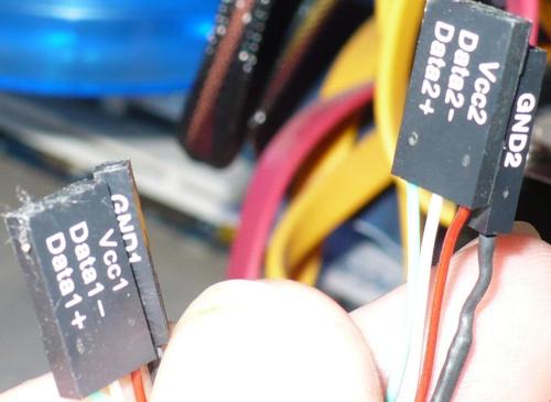
Ok, so here is my pic and i need help connecting these things right so when i put my flash in here it doesn't bomb out like the last one.
  • 0

#9
Adrenalin

Adrenalin

    Member

  • Topic Starter
  • Member
  • PipPipPip
  • 451 posts
Ok, so here is my pic and i need help connecting these things right so when i put my flash in here it doesn't bomb out like the last one.

Attached Thumbnails

  • Chassis_Connectors.JPG
  • Front_USB_Motherboard_Connectors.JPG

  • 0

#10
123Runner

123Runner

    Member 4k

  • Member
  • PipPipPipPipPipPipPip
  • 4,528 posts
Ok, what you have is 2 USB headers on the board for extra USB ports.

You can use either "USB 1 or USB 2". Each has the cabability of running 2 receptacles.

Lets use USB 1.
Take the cable that has "data1" marked on it. Place that on the top row with "Vcc1" in the upper right pin. The label will be facing up so you can read it. That will take care of the top 3 pins.
Take "gnd1" and put that on the 4th pin from the right. There will be no pin or socket on the far left/ top.

On the bottom row, that is where the socket with "data2" and "gnd2" go. The orientation is the same. You will not be able to read the label because it is blocked by the first one.
Vcc2 goes on the bottom right. The gnd2 is the 4th pin from the right.
You will have 1 extra pin on the header. That has nothing on it.
  • 0

#11
Adrenalin

Adrenalin

    Member

  • Topic Starter
  • Member
  • PipPipPip
  • 451 posts
Thanks,

However it's still not working? Vcc1 is at the top and to the right, if you looking at the picture. Below that s the vcc2 etc as above.

The top row, to the very left is empty, and the same at the bottom.

I'm quite sure i've double checked it and it looks right as per the instructions?

Perhaps I should resort the 'the manual'...
  • 0


Similar Topics

0 user(s) are reading this topic

0 members, 0 guests, 0 anonymous users

As Featured On:

Microsoft Yahoo BBC MSN PC Magazine Washington Post HP