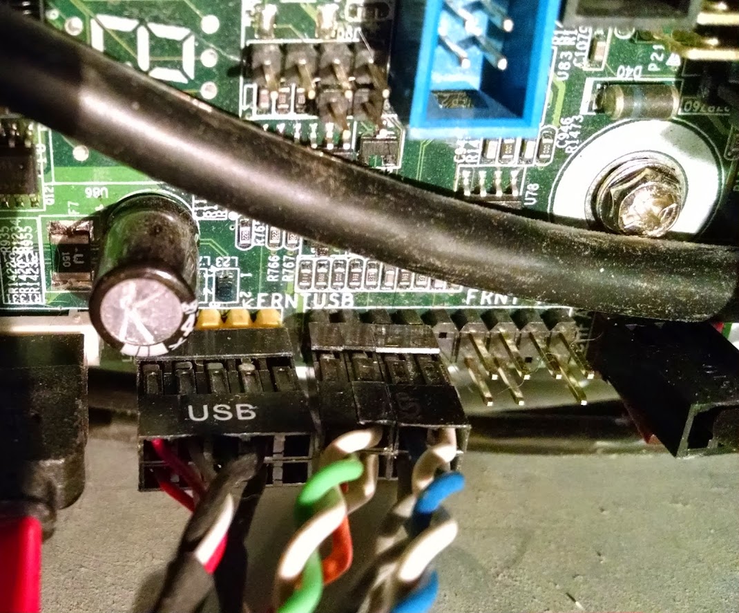
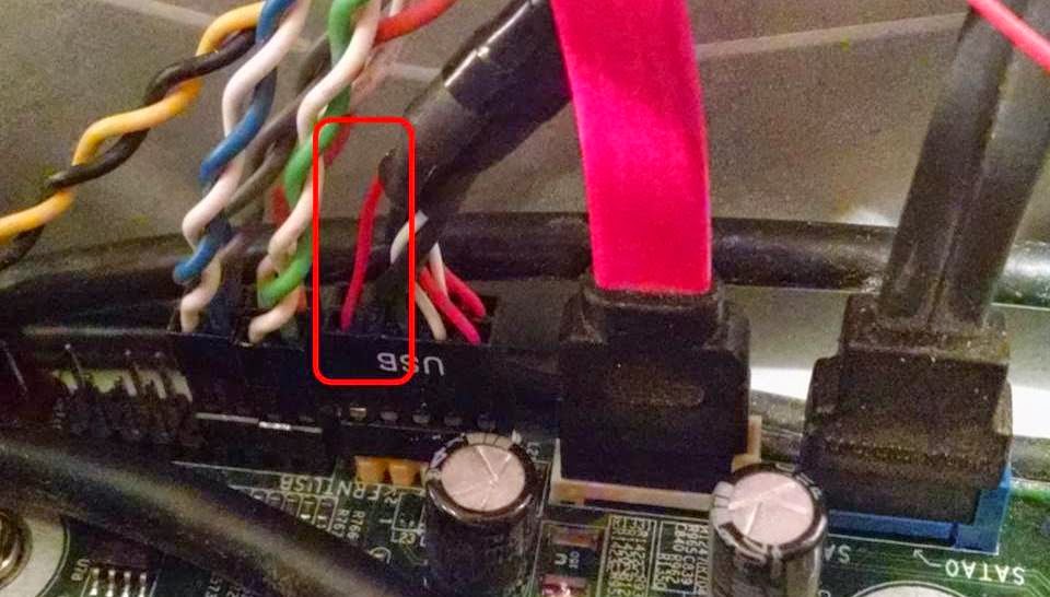
memory plays tricks with me and unless i see the motherboard manual i'm not 100% sure but think i'm correct in saying pin 4 and 9 are missing on your board.
start on the right top as you look at the picture for 1, below is 2 next top is 3 missing is 4 etc etc.
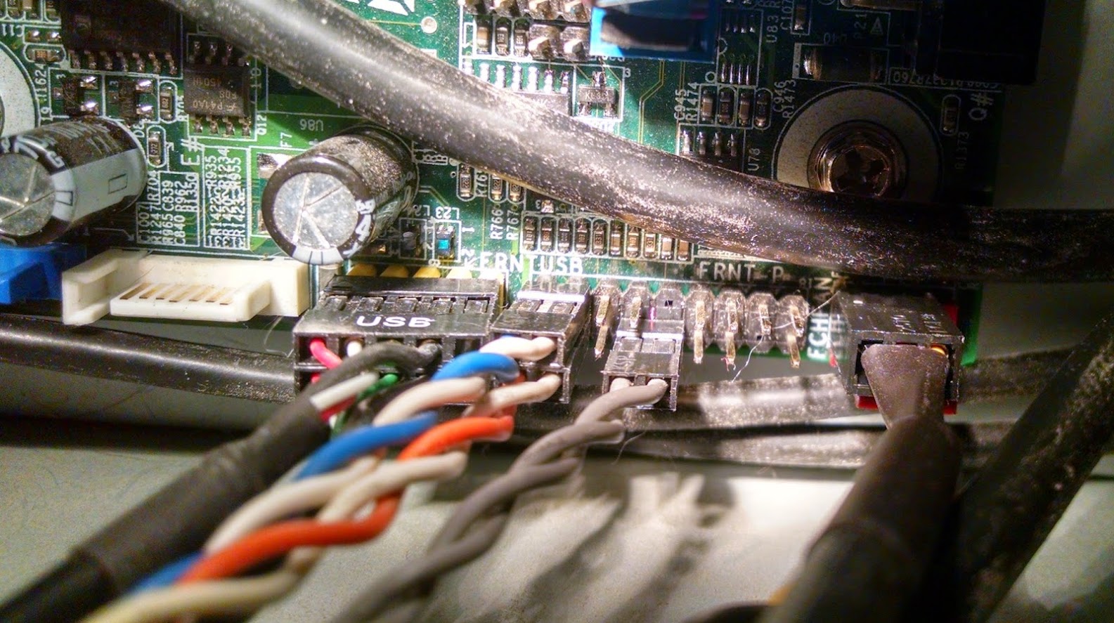
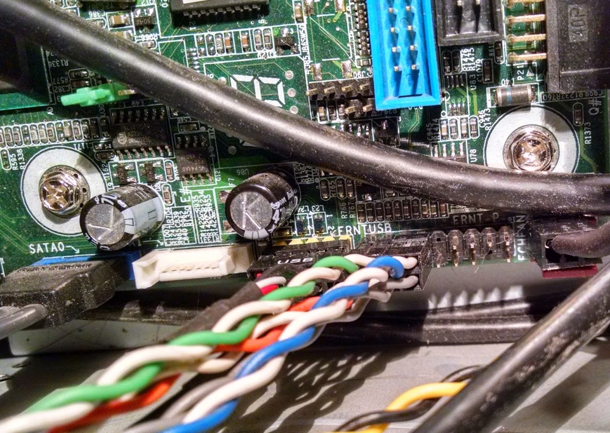
curious but was the picture taken when the motherboard was in and connected to the old case, asking because it has 3 cables connected so assume they are in the correct place unless you tried those positions and it didn't work and just took the picture with them still plugged in.
had a closer look at pic. and top right is pin 18. so far bottom left is pin 1.
so going by this.
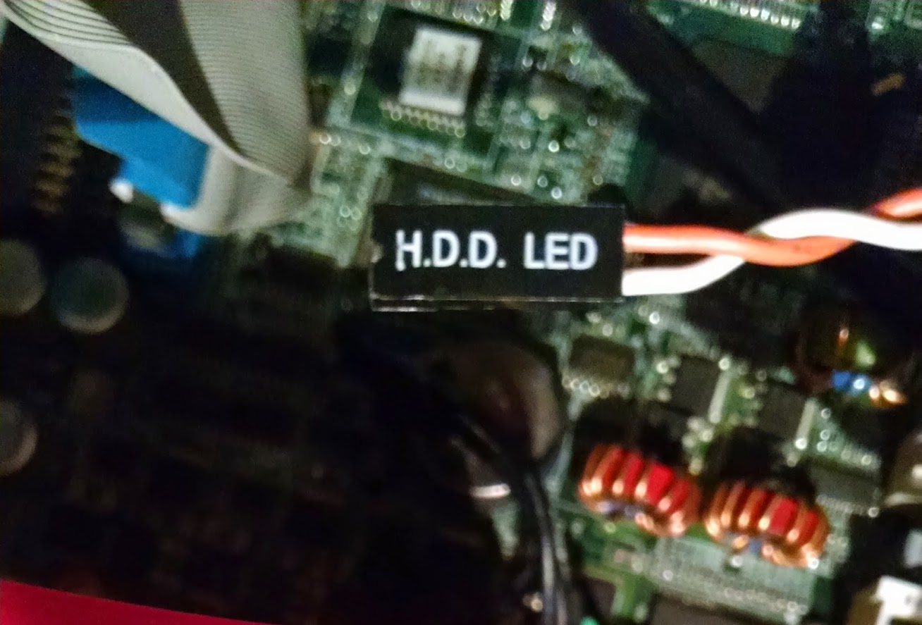
Pin 1 = Hard drive clear plastic lens bottom LED (which shows HD activity)… white wire, positive, LED anode wire.
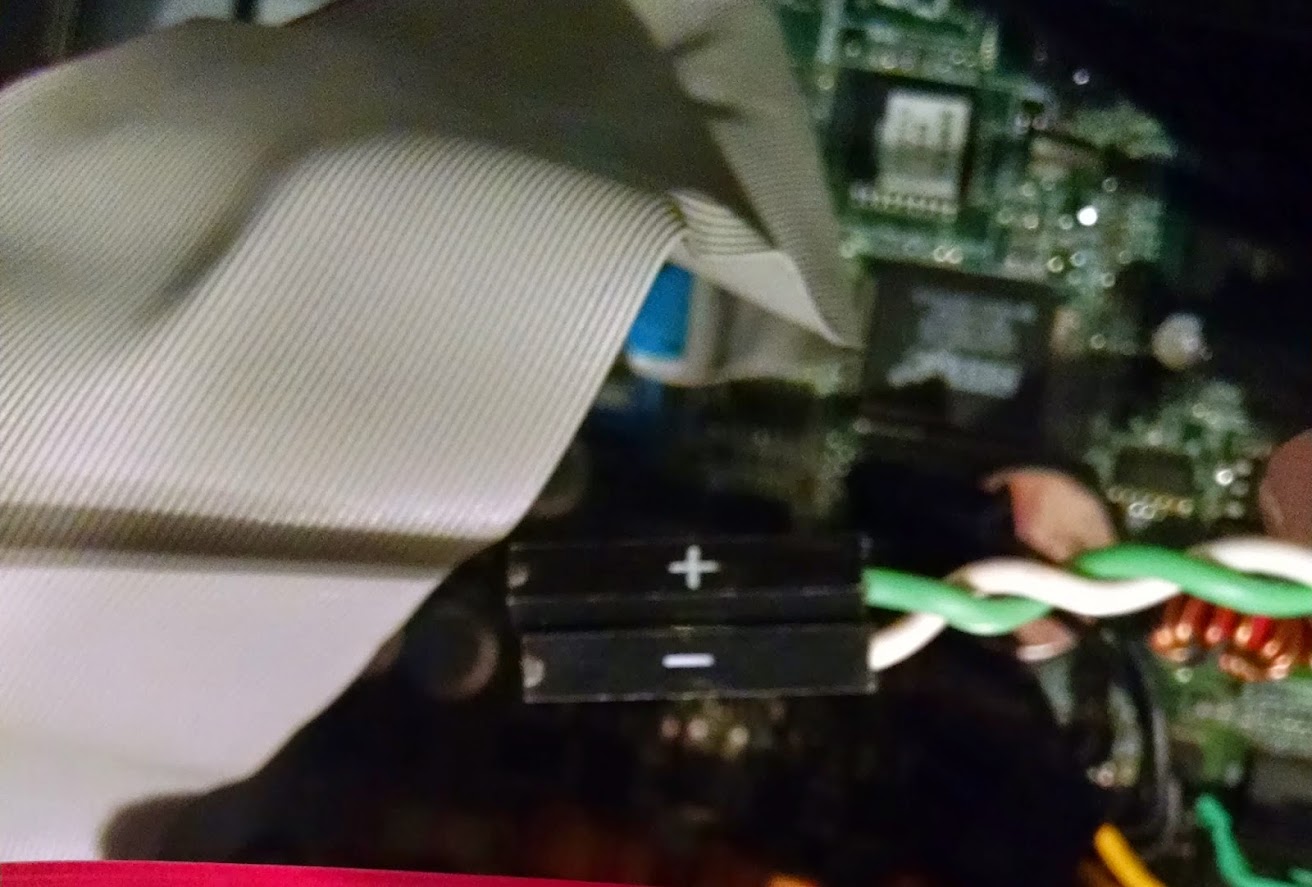
Pin 2 = Frosted lens "dual color" top LED (solid or blinking green LED, or orange motherboard error code signals) (one wire of front panel dual-color LED)… red wire. This is the set that I believe runs opposite polaritiy from the motherboard to either generate the usual green light, or the error orange code light signals. LED lights generally work with only one polarity in DC, but this one seems to have two different color LEDs built into one unit fed by two wires total.
Pin 3 = Hard drive clear plastic lens bottom LED (negative end, the LED's cathode wire)… green wire
Pin 4 = Frosted lens top LED Red (solid orange color LED) (other wire of front panel dual-color LED)… black wire
Pin 5 = No wire attached in xw6400. Ground.
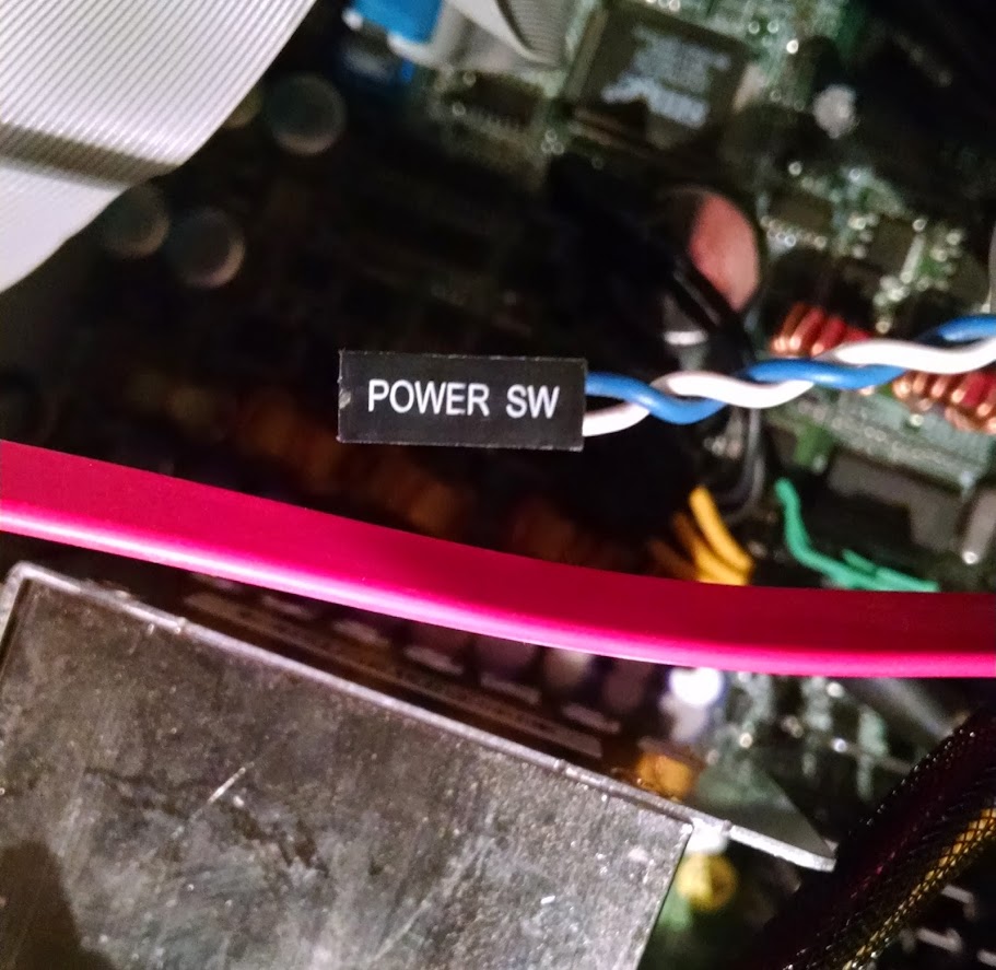
Pin 6 = Front panel switch for power on/off… thick white wire attached.. Positive.
Pin 7 = No wire attached in xw6400
Pin 8 = Front panel switch for power on/off… thick white wire attached. Ground.
Pin 9 = No wire attached in my xw6400. May be +5V
Pin 10 = Key (no pin on motherboard header; plastic filling the #10 hole in the receptacle)
Pin 11 = No wire attached in xw6400. Has gray wire of ambient air temperature thermisitor attached in xw6600 cable
Pin 12 = No wire attached in xw6400. Has brown wire of ambient air temperature thermisitor attached in xw6600 cable
Pin 13 = Orange wire, but not used in my xw6400. For hood sensor connector. Ground.
Pin 14 = Orange wire, but not used in my xw6400. For hood sensor connector.
Pin 15 = Key (no pin on the motherboard; plastic filling the #15 hole in the receptacle)
Pin 16 = Blue wire, but not used in my xw6400. For hood sensor connector.
Pin 17 = Internal speaker +… yellow wire
Pin 18 = Internal speaker - … yellow wire
quick way to check is to short out or connect the power sw to pins 6 and 8 and see if it turns on the pc, if it does then it looks correct.
now - are usually the same colour wire so i'd say the white wires are negative on your connections but according to that list pin 1 is + and white on his setup so don't know if i'd connect the hdd led to pins 1 and 3 with the white or orange wire on pin 1 with other on pin 3.
once i knew pins 6 and 8 started the pc i'd get a multimeter and check the polarity of those other pins to check if they are positive + or negative - before connecting any more wires.
depending on result of test, remember + goes to + and - goes to - for the led wires.
hdd led goes on pins 1 and 3
+ - goes on pins 2 and 4
power sw goes on pins 6 and 8
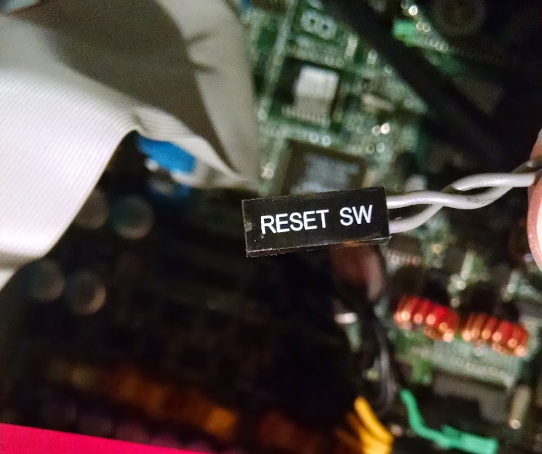
reset sw goes ?? 5 and 7 i'd guess

Edited by terry1966, 23 January 2015 - 02:28 PM.


 Sign In
 Create Account
