Jump to content

Welcome to Geeks to Go - Register now for FREE

Need help with your computer or device? Want to learn new tech skills? You're in the right place!
Geeks to Go is a friendly community of tech experts who can solve any problem you have. Just create a free account and post your question. Our volunteers will reply quickly and guide you through the steps. Don't let tech troubles stop you. Join Geeks to Go now and get the support you need!

How it Works Create Account
Photo

help needed for a cmoy amp


  • Please log in to reply

#16
Major Payne

Major Payne

    Retired Staff

  • Retired Staff
  • 5,307 posts
Would be nice if I can get this answered here on my own as I have been in electronics all my life and have a degree in it.

Since I don't know what was included in the kit parts and from the schematic I read, you have two options. Firstly, if you already have just the transformer (see comments below about transformer), you will need to built your own DC power supply. A power transformer that you need has 4 or 5 leads. The primary side is usually color-coded black. That's the 120 VAC side. Secondary side usually red for a 2 lead one or red with a third a different color denoting the center tap. Color-coding is standard, but not always followed.

Depending on whether it is a center-tapped transformer will determine what type of rectifier circuit will be needed. If the kit parts did not include additional parts for building the DC power supply, you will need to purchase them. I can draw up a schematic for the power supply once I have the details.

Secondly, the easiest method is to use an a/c adapter of the correct voltage/current rating. Your schematic shows amp operating at 14.7 volts. A good close a/c adapter would be a 12 volt rated at 1 to 1.5 amps. This will handle 12 watts and provide you with no drop out because of voltage drop. You will need a matching jack for the a/c adapter if you wish to not hot wire the adapter right to the amp. A plug/jack combo will allow you to unplug a/c adapter from amp.

Polarity is going to be a concern no matter which way you go. I hope you have a Digital Volt Meter (DVM) or some voltmeter to read dc so you can identify polarity should you go with the a/c adapter. Lots of times the plug polarity is marked on the adapter case or even the plug.

The transformer you have described sounds more like an audio type and not a power transformer.

Your best bet is to try to get some simple beginner's books on electronics/electricity. Will try to track down some online information for you.

Ron
  • 0

Advertisements


#17
uglymaggot

uglymaggot

    Member

  • Topic Starter
  • Member
  • PipPip
  • 97 posts
heres the contents of the kit
Resistors
R1-150E
R2-100E
R3-1E
P1-1M LOG

Capacitors
C1,7,9-100uF
C2,3,5-100uF/16V
C4-6K8pF
C6-1K5pF
C8,9-1000uF/25V

Misc
0-12V/500MA transformer (optional)
Heatsink

no points are given for the jacks & power
whats an audio transformer ?
the one i got has 4 blue wires 2 left & 2 right
  • 0

#18
Major Payne

Major Payne

    Retired Staff

  • Retired Staff
  • 5,307 posts
Compared parts list against schematic. Lots of differences in values on schematic and what you gave from parts list. The transformer is going to be troubling as you do list it as a 12-v, 500 mA one. With all 4 leads completely blue, there is no way I can tell you by post which is the primary or secondary. There are ways to ascertain which is which, but more complicated then I want to delve into here. Are you sure there are no different colored stripes on two of the blue leads? Hate to ask this, but you are not color blind are you or see colors differently then the true ones?

I'm worried that you are not identifying the resistors correctly as they should have a color code on the body of each. The values for the capacitors don't quite match up to schematic, which is not as worrisome as putting the wrong resistor in the wrong place and applying power.

I couldn't read the IC type from the schematic even blowing it up to 400% :). Your parts list didn't list the 4-ohm speaker either which makes me think the parts and amp don't go together as a kit. Was there a printed circuit board included?

Ron
  • 0

#19
zorba the geek

zorba the geek

    Member

  • Member
  • PipPipPip
  • 758 posts
Hi Ron!I hope you don't mind me butting in,i've used this chip a few times.it seems to work quiet well with 12V.To spare me the hassle of building a rectifiercircuit,i used a external powersupply(12V)from an HP printer.Again,sorry for butting in!Zorba
  • 0

#20
uglymaggot

uglymaggot

    Member

  • Topic Starter
  • Member
  • PipPip
  • 97 posts

Hate to ask this, but you are not color blind are you or see colors differently then the true ones?

No Ron i am not color blind :)
My schematic is slightly different :)

yes all wires are blue but oddly enough the two fine wires go to the mains & the thicker wires go to the circuit.(a friend who did electronics helped me with this)
we striped the diodes off an old speaker system & used them for the circuit then after numerous tests we got it to work so we hooked it up to a car speaker and it did pack quiet a punch for 7 watts :)
all that is left to do is to make a case and its done :wave:
Any how thanks for all the help Ron :) & sorry for all the trouble.

expect pics in a few weeks (got exams coming up so i'll be too busy to complete it right now)
  • 0

#21
zorba the geek

zorba the geek

    Member

  • Member
  • PipPipPip
  • 758 posts
Bravo,well done uglymaggot!I've cooked a few circuits when i started,so it's quiet a good feeling to get it working!There are a lot of books out there dealing with easy circuits for beginners!What's next,a stereoamp?Good luck with your exams
  • 0

#22
uglymaggot

uglymaggot

    Member

  • Topic Starter
  • Member
  • PipPip
  • 97 posts
Ya zorba the geek it is pretty cool to get it working and its my first circuit :wave:
if you know of any online site about this stuff it would be great :) ya i guess i'll go in for a 30watt stereoamp there is a cool kit available
one question though do all circuits use only 4 diodes or does it matter what the input/output is??

Thanks because i'll need luck, alot of it
  • 0

#23
Major Payne

Major Payne

    Retired Staff

  • Retired Staff
  • 5,307 posts

Hi Ron!I hope you don't mind me butting in,i've used this chip a few times.it seems to work quiet well with 12V.To spare me the hassle of building a rectifiercircuit,i used a external powersupply(12V)from an HP printer.Again,sorry for butting in!Zorba

Think I suggested that in post #16:

Secondly, the easiest method is to use an a/c adapter of the correct voltage/current rating. Your schematic shows amp operating at 14.7 volts. A good close a/c adapter would be a 12 volt rated at 1 to 1.5 amps. This will handle 12 watts and provide you with no drop out because of voltage drop. You will need a matching jack for the a/c adapter if you wish to not hot wire the adapter right to the amp. A plug/jack combo will allow you to unplug a/c adapter from amp.


No problem with butt-ins if they are constructive. :)

Glad to hear you have the amp finished and working uglymaggot. When you asked about all circuits using 4 diodes, I take it you were referring to power supply circuits. There are many rectifier convenient packages available for these circuits if building from scratch so you donn't have to work with 4 individual diodes. I usually like to go with a good a/c adapter with a slightly higher voltage and clamp it to the rated voltage with a good voltage regulator circuit. Improves filtering. Every one has their own design methods and I have zapped a few projects in my day. Worse was a nice all band ham transmitter. :wave:

Ron

Edited by Major Payne, 04 October 2007 - 11:08 PM.

  • 0

#24
Major Payne

Major Payne

    Retired Staff

  • Retired Staff
  • 5,307 posts

one question though do all circuits use only 4 diodes or does it matter what the input/output is??

Check out the packages for rectifier packages: JameCo

Specs on one

Don't know if ordering a free catalog would help you, but these catalogs make good references. Lots of engineering data in them:

JameCo Catalog
Newark Catalog
Newark's Online Catalog


Ron

Edited by Major Payne, 05 October 2007 - 03:12 AM.

  • 0

#25
uglymaggot

uglymaggot

    Member

  • Topic Starter
  • Member
  • PipPip
  • 97 posts
thanks Ron
i will have pics put up as soon as possible next is a 30 watt stereo amp :)
forgive me for my ignorance but i did'nt know you got rectifiers like that because we used 4 individual diodes from a 12 pc speaker

Edited by uglymaggot, 05 October 2007 - 03:11 AM.

  • 0

Advertisements


#26
Major Payne

Major Payne

    Retired Staff

  • Retired Staff
  • 5,307 posts
Looking forward to pix. here's an old company that use to make kits, but now they provide education kits: Heathkit Co.. Really loved those kits when I was a kid, but this is the only part of the company still in business.

A newer source: Electronic Kits

Here's a site with a free series of textbooks on the subjects of electricity and electronics. You can download printable versions of each book in PDF.

Also free: Electronics Theory

Online tutorials

Should be enough to get you started. Still, buying or visiting a local library would be good way to learn more.

Ron

Edited by Major Payne, 05 October 2007 - 04:23 AM.

  • 0

#27
uglymaggot

uglymaggot

    Member

  • Topic Starter
  • Member
  • PipPip
  • 97 posts
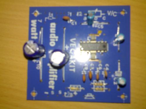
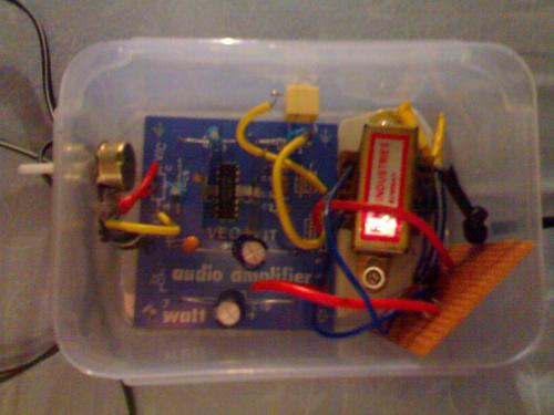
here are the pics of the 7 watt amp

Attached Thumbnails

  • circuit.jpg
  • top_of_circuit.jpg

  • 0

#28
uglymaggot

uglymaggot

    Member

  • Topic Starter
  • Member
  • PipPip
  • 97 posts
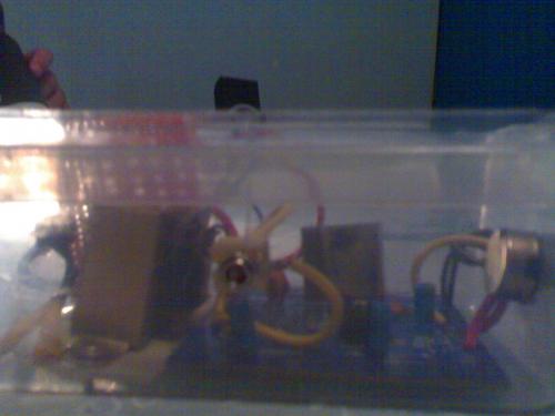
pics continued

Attached Thumbnails

  • side_view.jpg

  • 0

#29
zorba the geek

zorba the geek

    Member

  • Member
  • PipPipPip
  • 758 posts
:wave: :)
  • 0

#30
uglymaggot

uglymaggot

    Member

  • Topic Starter
  • Member
  • PipPip
  • 97 posts
thanks Zobra the geek put in all the finishing touches today ([beep]exams this is more important)
  • 0


Similar Topics

0 user(s) are reading this topic

0 members, 0 guests, 0 anonymous users

As Featured On:

Microsoft Yahoo BBC MSN PC Magazine Washington Post HP